track and hold circuit in adc
(a) The bottom-plate sampling and (b) the top-plate sampling techniques. 9 Pics about (a) The bottom-plate sampling and (b) the top-plate sampling techniques : (PDF) An experimental 0.6-V 57.5-fJ/conversion-step 250-kS/s 8-bit rail, Appendix B – Block Schematics and also MAX104 ±5V, 1Gsps, 8-Bit ADC with On-Chip 2.2GHz Track/Hold Amplifier.
(a) The Bottom-plate Sampling And (b) The Top-plate Sampling Techniques
 www.researchgate.net
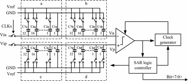
adc sar
MAX106 ±5V, 600Msps, 8-Bit ADC With On-Chip 2.2GHz Bandwidth Track/Hold
 www.maximintegrated.com
circuit chip operating typical adc bit
(PDF) An Experimental 0.6-V 57.5-fJ/conversion-step 250-kS/s 8-bit Rail
 www.researchgate.net
proposed circuit hold track adc bit rail
An 8-bit 500-MS/s Asynchronous Single-channel SAR ADC In 65 Nm CMOS
 link.springer.com
sar adc cmos asynchronous nm ms fig channel bit single
MAX104 ±5V, 1Gsps, 8-Bit ADC With On-Chip 2.2GHz Track/Hold Amplifier
 www.maximintegrated.com
adc 2ghz 5v amplifier chip hold track bit enlarge
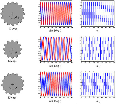
The Vernier Scale Goes Digital | FierceElectronics
 www.fierceelectronics.com
vernier goes scale digital angle signals sine phase three
Appendix B – Block Schematics
 www.eecg.toronto.edu
MAX1658 Datasheet - 350mA, 16.5V Input, Low-dropout Linear Regulators
 www.digchip.com
datasheet
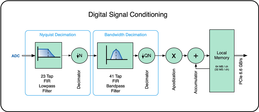
Plane Wave – Vol. 4, Issue 1 – Signal Conditioning In The Vantage
 verasonics.com
signal conditioning system digital vantage research diagram block ultrasound adds flexibility efficiency receive path projects wave representing figure data
Appendix b – block schematics. Circuit chip operating typical adc bit. (a) the bottom-plate sampling and (b) the top-plate sampling techniques